ICOM IC-R2 Radio Scanner
From Inside Electronics
This is the ICOM IC-R2 scanner. It is a small hand-held scanner that receives AM and FM signals in the range 500kHz to 1.3GHz. This covers most public transmissions, except higher frequency satellite signals. The unit has a built in speaker and a detachable wideband antenna. It has 8 memory banks of 50 channels each and can store 25 scan ranges. It supports duplex receiving, where a conversation is held on two frequencies in the same band, and Continuous Tone Coded Squelch System (CTCSS) where the squelch can be set to open a channel only if it has the correct tone transmitted with it. This system allows a several radios to use the same frequency, but filter the traffic for only those that carry the required tone.
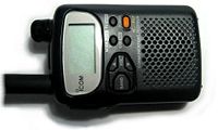
Front of Radio scanner
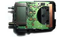
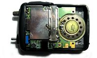
Front with cover removed
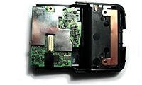
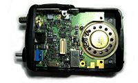
Front with main board removed


The photos above show the front of the unit, with the front cover removed and then with the display circuit board removed. All the control and display logic is managed by the large surface mount IC under the LCD screen in the middle photo. The push button contacts can be seen to the right of the screen, followed by a gap for the speaker. The right hand photo shows the RF board behind the display circuit board. This uses a connector to neatly link the two circuit boards together. The RF board uses a metal screen cover on both sides to reduce interference. The surface mount circuitry under these screens is shown further down the page.
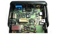
The photos below show the back of the unit, with the back cover removed and with the RF circuit board removed. The large speaker can be seen to the right, and the metal cover over the Radio board can be seen to the left. The RF board plugs into the socket on the main board, which can be seen in the right hand photo. The headphone socket between the antenna and dial can be used to link the scanner to a PC via the serial port (see links below). Good reception requires the scanner to be held in the hand, giving a good ground for the antenna.
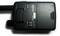
Back of Radio scanner
Back with cover removed
Back with RF board removed


The right hand photo above shows the large number of discrete components used on the main board. The RF board is packed with discrete components on both sides and demodulates the incoming signal on the frequency selected by the control board. The control board probably just deals with low frequency signal processing (e.g. CTCSS) and audio, as well as the digital interface and control. The 4MHz crystal is used for the microprocessor clock.
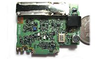
If you were wondering how the IC-R2 can do so much in such a small package, look at the photos below. The left photo is a close up of the main board. The dial is at the top left. The headphone and PC link socket is in the centre. The antenna connection is in the top right. The front of the RF board is shown in the middle, with the plug to connect to the main board in the centre. The metal screen has not been removed, but underneath the dense covering of components continues. A 10 pence piece is shown for scale. The right hand photo shows the other side of the RF board. This time the metal screen has been removed and the path from the antenna in the bottom left to the demodulator in the top right can be seen. The demodulator has its own screen, to reduce the chance of a scanner detector measuring the frequency being demodulated.
Main board

Front of RF board
Back of RF board


I currently have the following channels programmed into my scanner, the frequencies apply to the UK:
| Bank 0 | Citizens Band (CB) channels | 26.965MHz to 27.855MHz in 10KHz steps |
| Bank 1 | Band II FM Radio stations | 87.6MHz to 107.9MHz |
| Bank 2 | Airband channels | 108MHz to 136.9MHz |
| Bank 3 | PBR Radios (Taxis etc.) | 165.05MHz to 173.0375MHz in 12.5KHz steps |
| Bank 0* | PMR446 Radios | 446.00625MHz to 446.09375MHz in 12.5KHz steps |
| Bank 1* | Band IV TV channels 21 to 68 | 477.25MHz to 853.25MHz in 8MHz steps |
| Bank 2* | Empty | |
| Bank 3* | Frequencies to ignore when scanning (a feature of the IC-R2) | |
Links
- Review of the IC-R2 Scanner - Including instructions and specifications
- Connecting the IC-R2 to a PC - How to make your own serial cable, with cloning software
- http://www.ic-r2.com/ - Buy the serial cable and software for connecting to a PC
- The Radio Spectrum - A complete list of frequencies mirrored at http://www.wibble.co.uk/