File list
From Inside Electronics
This special page shows all uploaded files.
| Date | Name | Thumbnail | Size | User | Description | Versions |
|---|---|---|---|---|---|---|
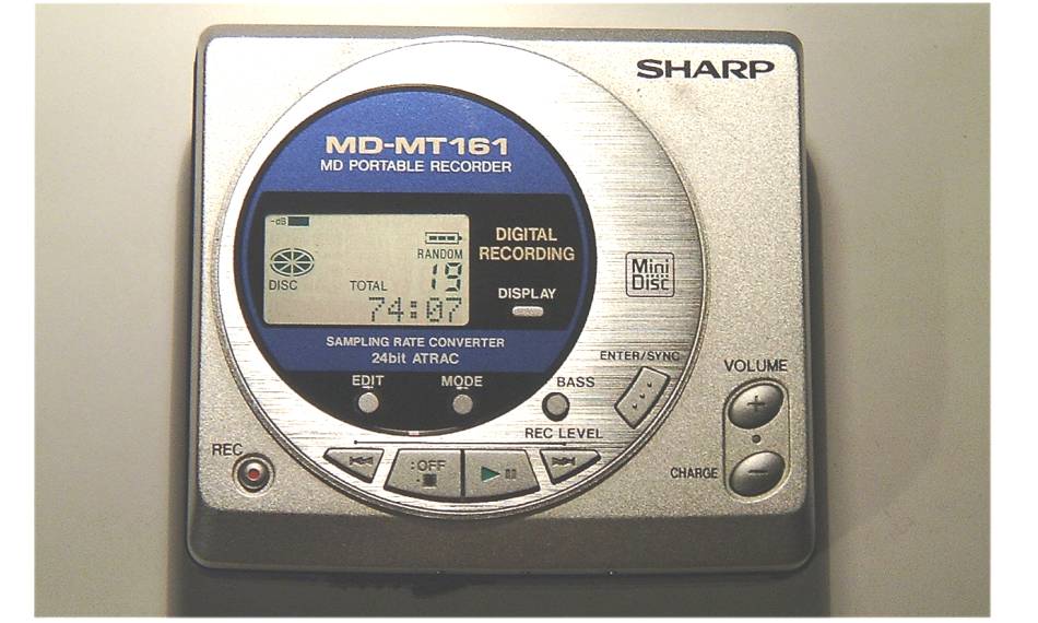
| 22:06, 21 August 2009 | Minidisc front1.jpg (file) |  |
71 KB | Tim | Photo of the front of the Sharp MD-MT161E Minidisc player. | 1 |
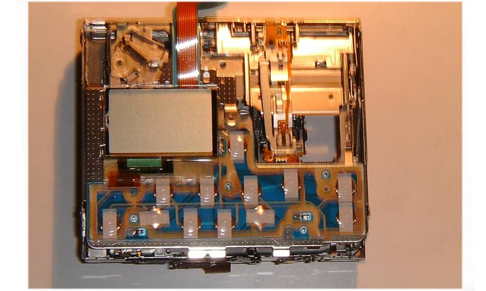
| 23:03, 21 August 2009 | Minidisc front2.jpg (file) |  |
70 KB | Tim | Photo of the front of the Sharp MD-MT161E Minidisc player with the cover removed. | 1 |
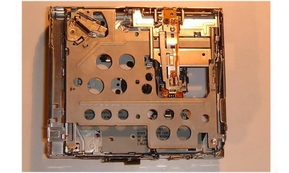
| 23:03, 21 August 2009 | Minidisc front3.jpg (file) |  |
72 KB | Tim | Photo of the front of the Sharp MD-MT161E Minidisc player with the cover and screen removed. | 1 |
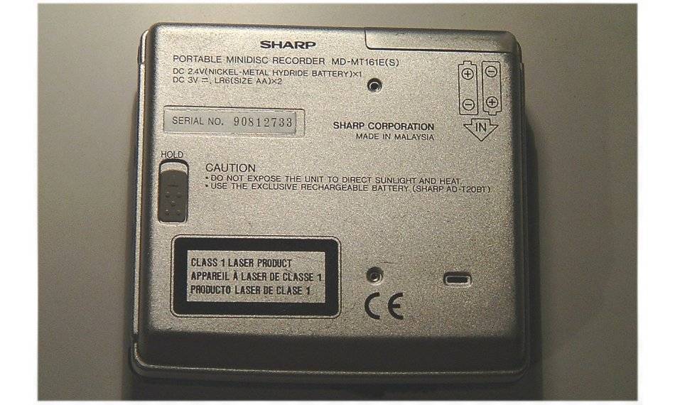
| 19:13, 23 August 2009 | Minidisc back1.jpg (file) |  |
88 KB | Tim | Photo of the back of a Sharp MD-MT161E Minidisc Player. | 1 |
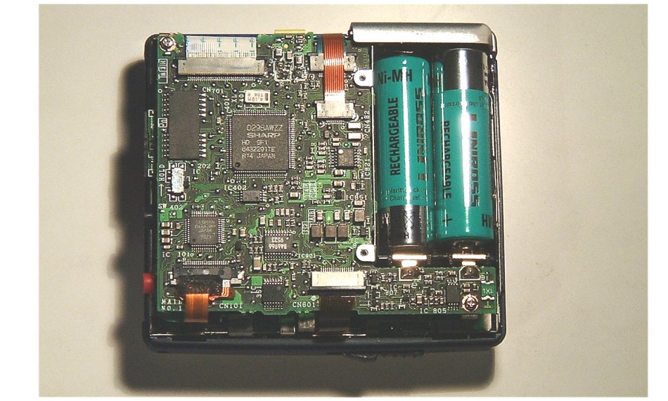
| 19:15, 23 August 2009 | Minidisc back2.jpg (file) |  |
120 KB | Tim | Photo of the front of the Sharp MD-MT161E Minidisc player with the cover removed. | 1 |
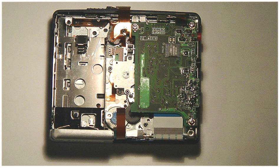
| 19:16, 23 August 2009 | Minidisc back3.jpg (file) |  |
79 KB | Tim | Photo of the front of the Sharp MD-MT161E Minidisc player with the cover and digital circuit board removed. | 1 |
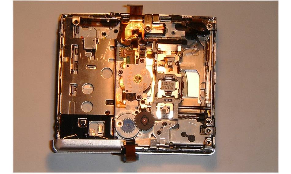
| 19:17, 23 August 2009 | Minidisc back4.jpg (file) |  |
77 KB | Tim | Photo of the back of the Sharp MD-MT161E Minidisc player with the cover and both circuit boards removed. | 1 |
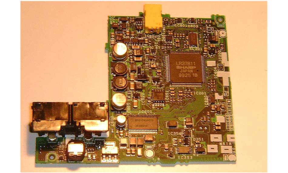
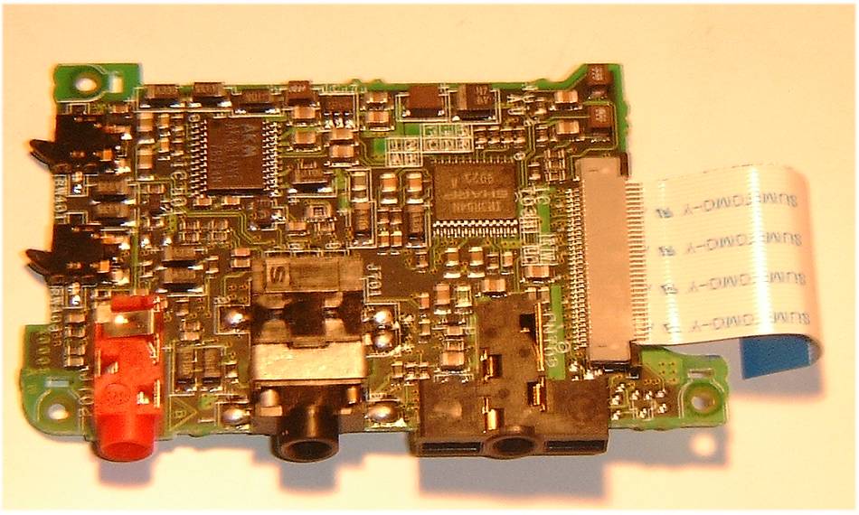
| 20:07, 23 August 2009 | Minidisc board1.jpg (file) |  |
80 KB | Tim | Digital circuit board from the Sharp MD-MT161E Minidisc player. | 1 |
| 20:08, 23 August 2009 | Minidisc board2.jpg (file) |  |
92 KB | Tim | Analogue circuit board from the Sharp MD-MT161E Minidisc player. | 1 |
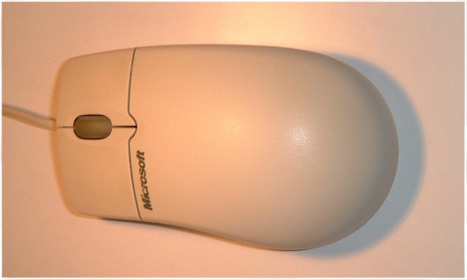
| 19:53, 24 August 2009 | Mouse 1.jpg (file) |  |
52 KB | Tim | Top view of Microsoft Intelli Ball Mouse | 1 |
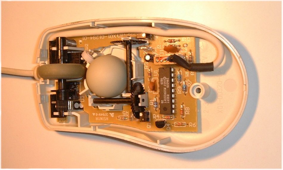
| 19:54, 24 August 2009 | Mouse 2.jpg (file) |  |
85 KB | Tim | Top view of Microsoft Intelli Ball Mouse with cover removed | 1 |
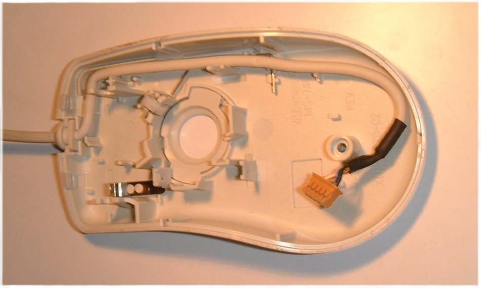
| 19:57, 24 August 2009 | Mouse 3.jpg (file) |  |
68 KB | Tim | Top view of a Microsoft Intelli Ball Mouse with cover and circuit board removed. | 1 |
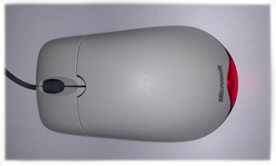
| 19:59, 24 August 2009 | Mouse top1.jpg (file) |  |
28 KB | Tim | Top view of a Microsoft IntelliEye Optical Mouse. | 1 |
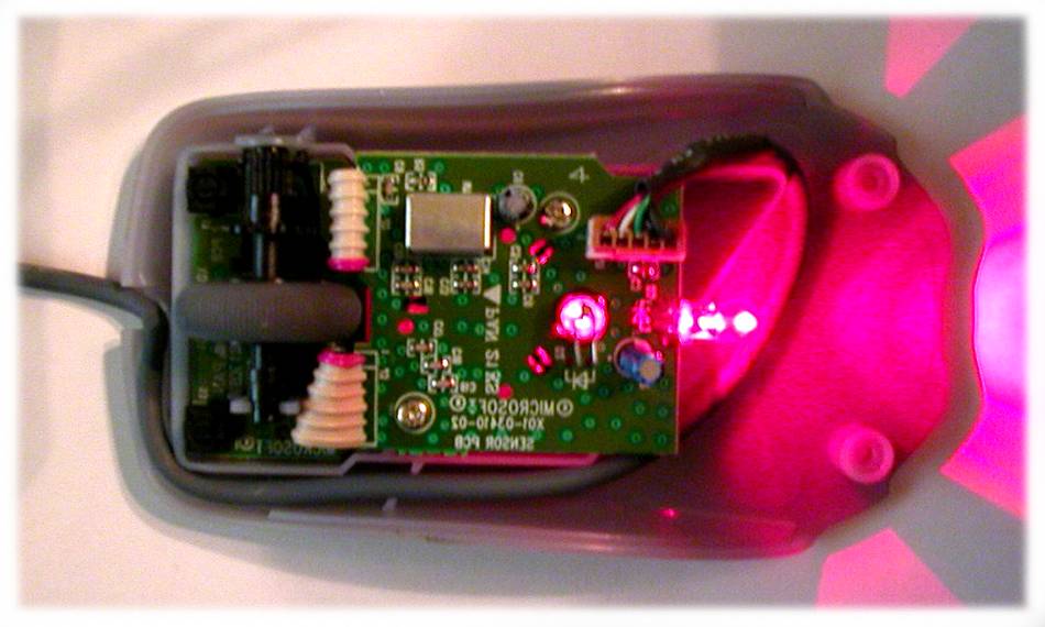
| 20:00, 24 August 2009 | Mouse top2.jpg (file) |  |
59 KB | Tim | Top view of a Microsoft IntelliEye Optical Mouse with the cover removed. | 1 |
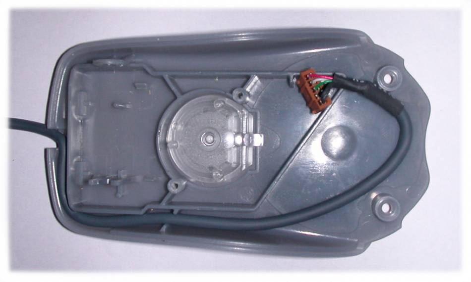
| 20:01, 24 August 2009 | Mouse top3.jpg (file) |  |
41 KB | Tim | Top view of a Microsoft IntelliEye Optical Mouse with the cover and circuit board removed. | 1 |
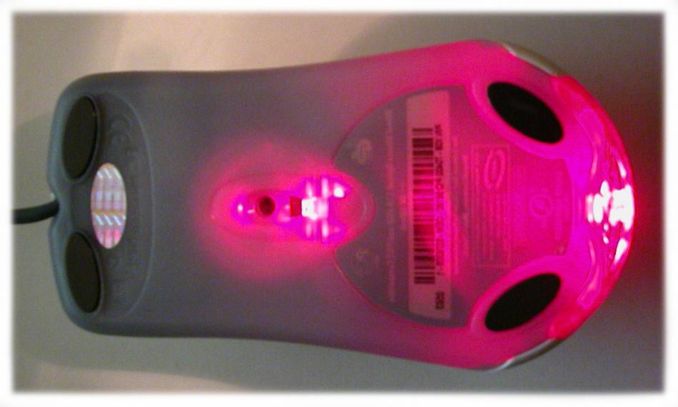
| 20:03, 24 August 2009 | Mouse bottom1.jpg (file) |  |
48 KB | Tim | Bottom view of a Microsoft IntelliEye Optical Mouse. | 1 |
| 20:04, 24 August 2009 | Mouse bottom2.jpg (file) |  |
46 KB | Tim | Bottom view of the circuit board from a Microsoft IntelliEye Optical Mouse. | 1 |
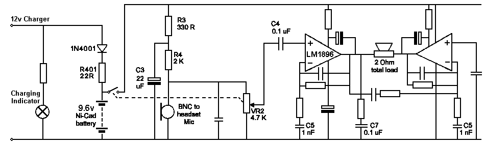
| 20:30, 24 August 2009 | NKCoxBox Amplifier Circuit.png (file) |  |
5 KB | Tim | Circuit diagram for the amplifier in a Nielsen Kellerman Cox Box. | 1 |
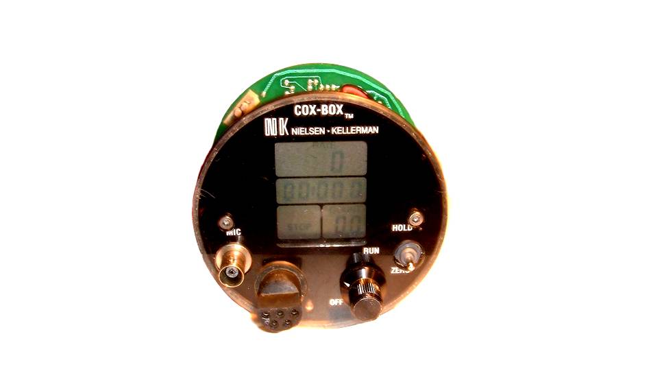
| 20:36, 24 August 2009 | NKCoxBox Front.jpg (file) |  |
29 KB | Tim | Front of a Nielsen Kellerman Cox Box with the case removed. | 1 |
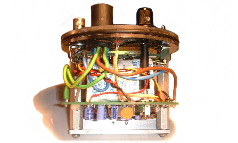
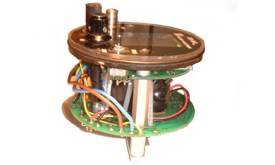
| 20:37, 24 August 2009 | NKCoxBox Side1.jpg (file) |  |
49 KB | Tim | Side of a Nielsen Kellerman Cox Box with the case removed. | 1 |
| 20:37, 24 August 2009 | NKCoxBox Side2.jpg (file) |  |
41 KB | Tim | Side of a Nielsen Kellerman Cox Box with the case removed. | 1 |
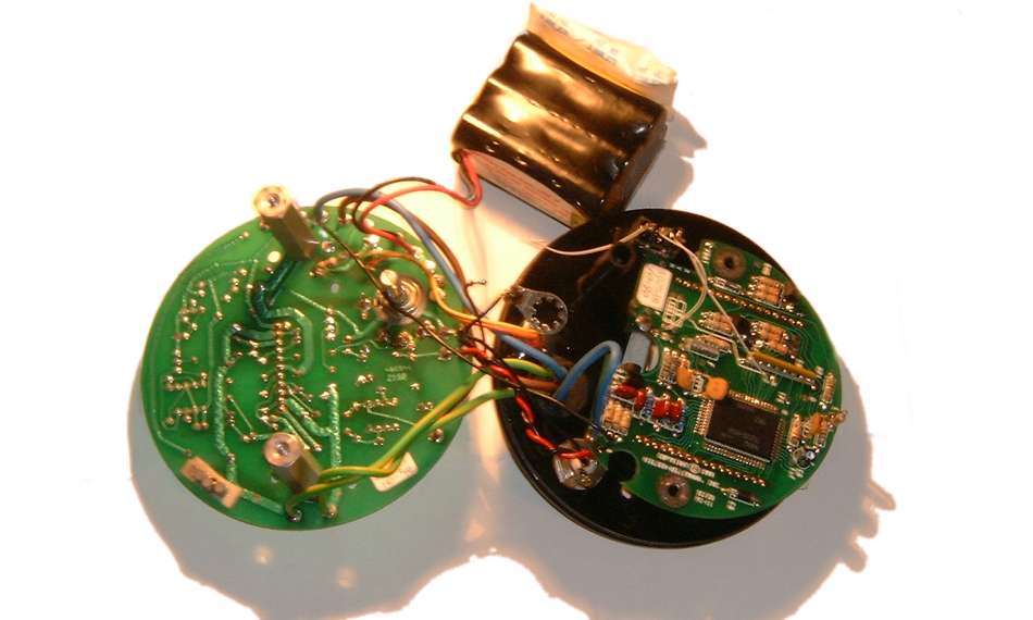
| 20:38, 24 August 2009 | NKCoxBox OpenedUp.jpg (file) |  |
46 KB | Tim | Nielsen Kellerman Cox Box opened up showing circuit boards. | 1 |
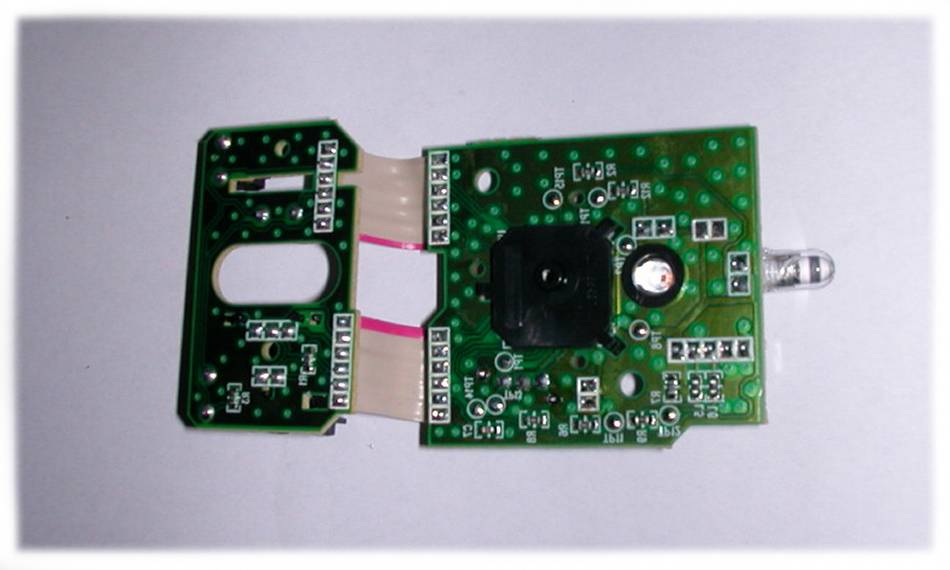
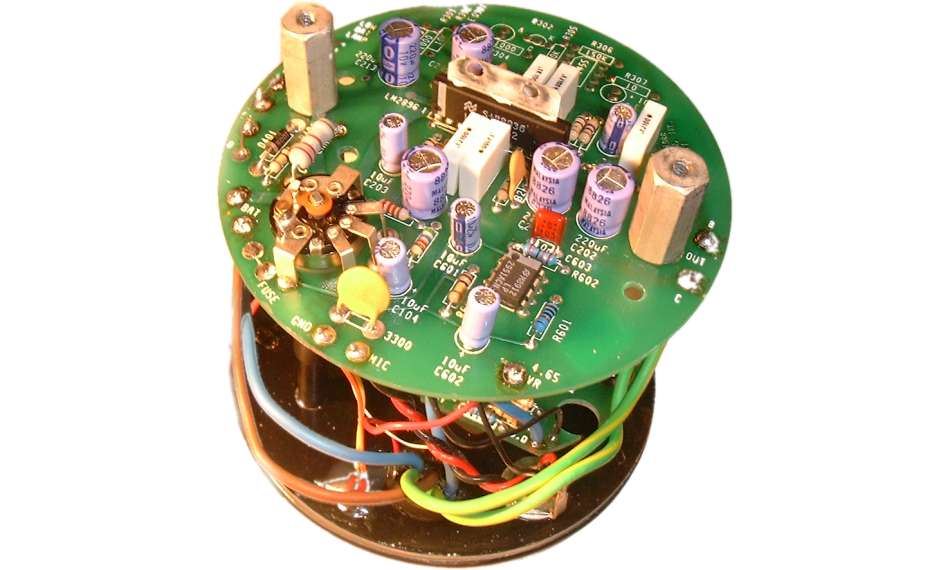
| 20:38, 24 August 2009 | NKCoxBox Amplifier.jpg (file) |  |
52 KB | Tim | Amplifier circuit board from a Nielsen Kellerman Cox Box. | 1 |
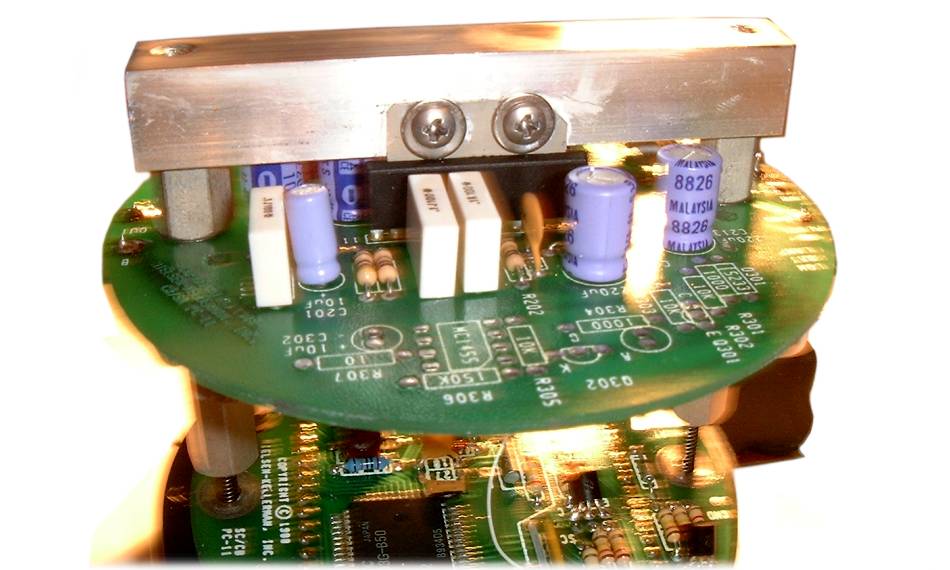
| 20:39, 24 August 2009 | NKCoxBox Heatsink.jpg (file) |  |
67 KB | Tim | Heatsink mounting from inside a Nielsen Kellerman Cox Box. | 1 |
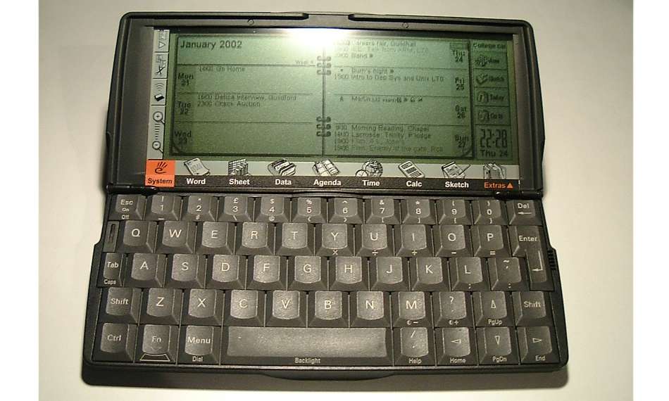
| 07:08, 25 August 2009 | Psion Front 1.jpg (file) |  |
62 KB | Tim | Front of open Psion 5 showing screen and keyboard. | 1 |
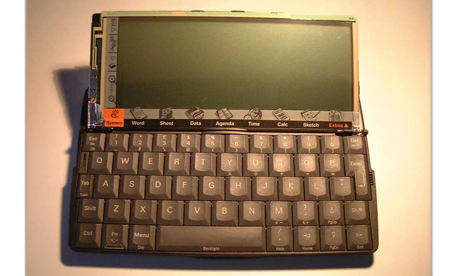
| 07:09, 25 August 2009 | Psion Front 2.jpg (file) |  |
47 KB | Tim | Front of open Psion 5 with the case removed. | 1 |
| 07:10, 25 August 2009 | Psion Front 3.jpg (file) |  |
54 KB | Tim | Front of open Psion 5 with screen removed. | 1 |
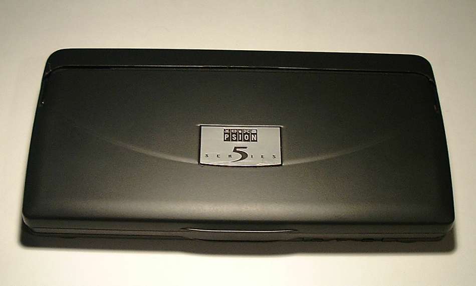
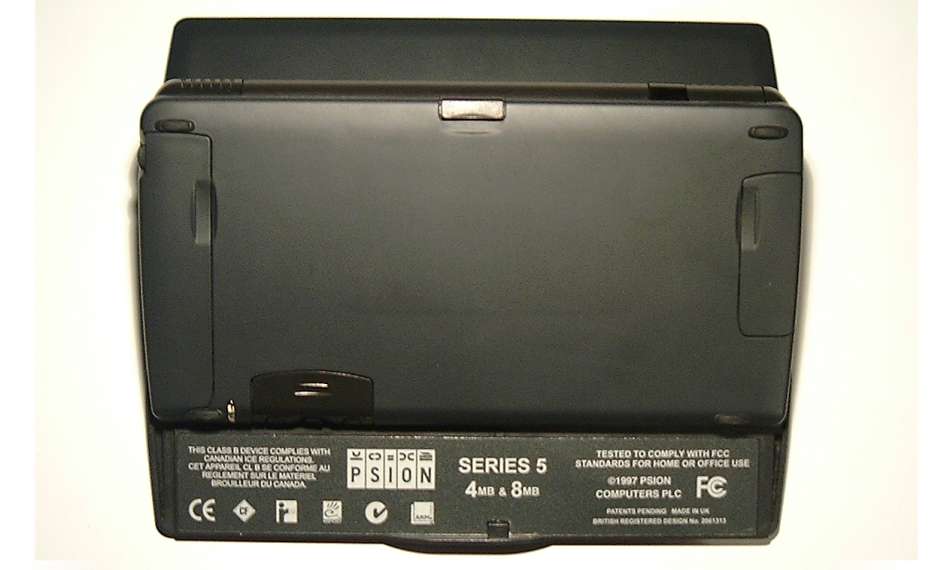
| 07:11, 25 August 2009 | Psion Top 1.jpg (file) |  |
31 KB | Tim | Top of closed Psion 5 showing badge. | 1 |
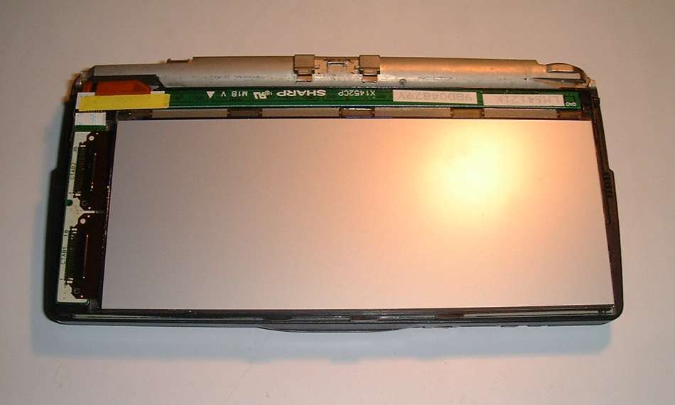
| 07:11, 25 August 2009 | Psion Top 2.jpg (file) |  |
47 KB | Tim | Top of closed Psion 5 with case removed. | 1 |
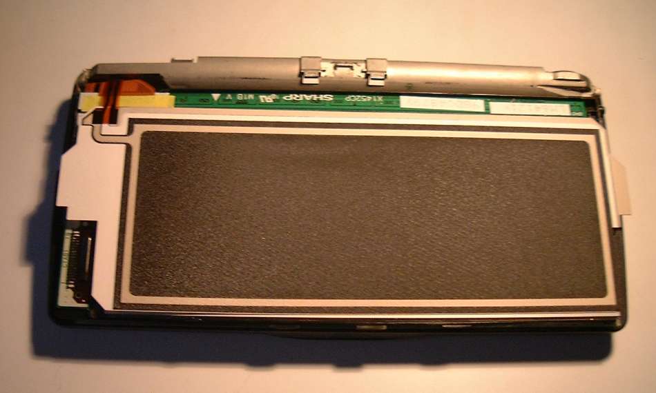
| 07:12, 25 August 2009 | Psion Top 3.jpg (file) |  |
32 KB | Tim | Top of closed Psion 5 with case and backlight removed, showing back of screen. | 1 |
| 07:14, 25 August 2009 | Psion Screen.jpg (file) |  |
33 KB | Tim | Psion 5 screen and touch sensitive membrane. | 1 |
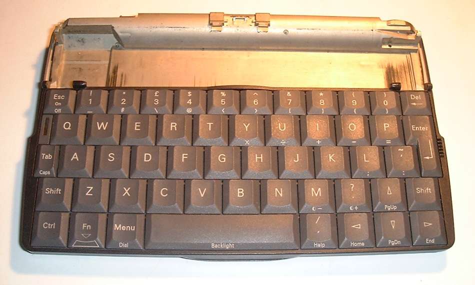
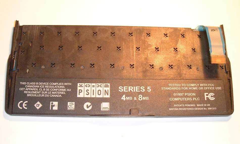
| 07:15, 25 August 2009 | Psion Keyboard.jpg (file) |  |
54 KB | Tim | Underside of Psion 5 keyboard. | 1 |
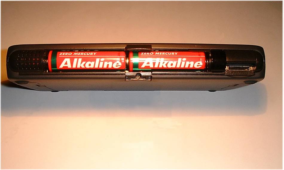
| 07:16, 25 August 2009 | Psion Batteries.jpg (file) |  |
44 KB | Tim | Psion 5 Battery compartment. | 1 |
| 07:17, 25 August 2009 | Psion Bottom 1.jpg (file) |  |
36 KB | Tim | Bottom of open Psion 5. | 1 |
| 07:18, 25 August 2009 | Psion Bottom 2.jpg (file) |  |
131 KB | Tim | Bottom of open Psion 5 with case removed. | 1 |
| 07:19, 25 August 2009 | Psion Bottom 3.jpg (file) |  |
104 KB | Tim | Bottom of Psion 5 with case and frame removed. | 1 |
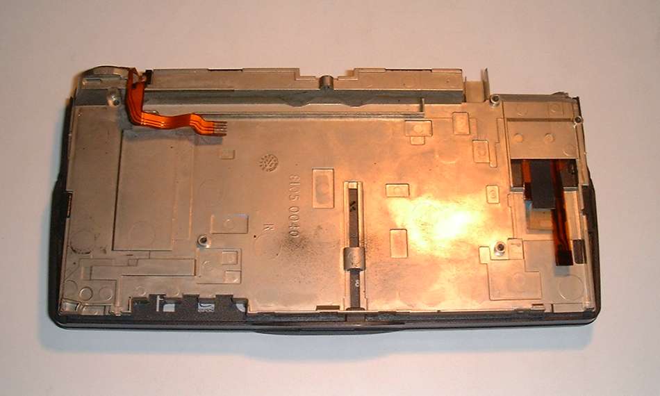
| 07:20, 25 August 2009 | Psion Top 4.jpg (file) |  |
40 KB | Tim | Top of Psion 5 with screen and keyboard removed. | 1 |
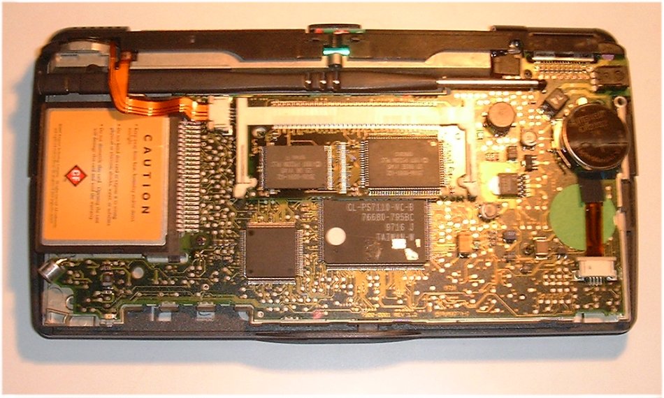
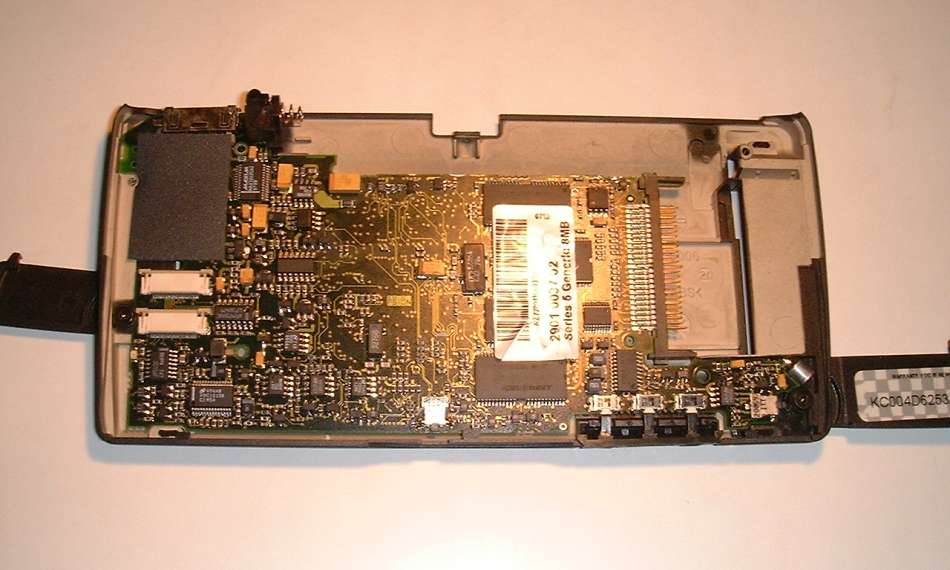
| 07:21, 25 August 2009 | Psion Board 1.jpg (file) |  |
61 KB | Tim | Psion 5 circuit board in bottom half of case. | 1 |
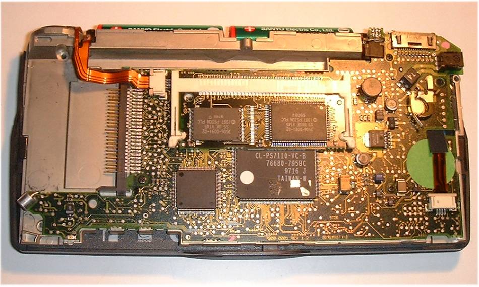
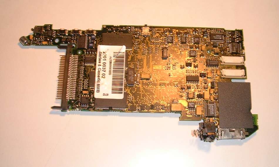
| 07:21, 25 August 2009 | Psion Board 2.jpg (file) |  |
57 KB | Tim | Psion 5 circuit board. | 1 |
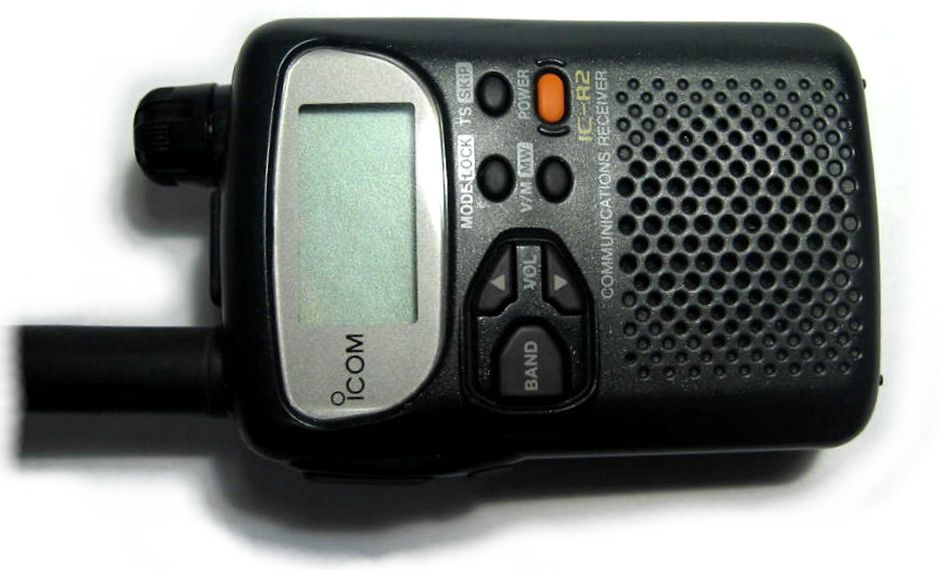
| 08:30, 25 August 2009 | IC-R2 Front1.jpg (file) |  |
63 KB | Tim | Front of the IC-R2 hand held radio scanner. | 1 |
| 08:30, 25 August 2009 | IC-R2 Front2.jpg (file) |  |
74 KB | Tim | Front of the IC-R2 hand held radio scanner with the cover and speaker removed. | 1 |
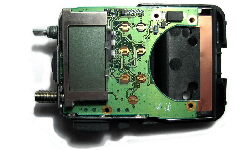
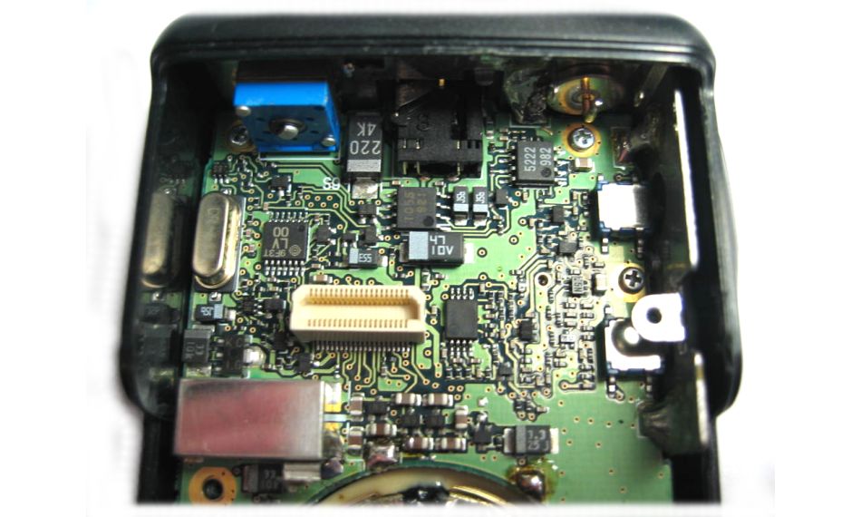
| 08:31, 25 August 2009 | IC-R2 Front3.jpg (file) |  |
70 KB | Tim | Front of the IC-R2 hand held radio scanner with the main circuit board removed, showing the RF circuit board. | 1 |
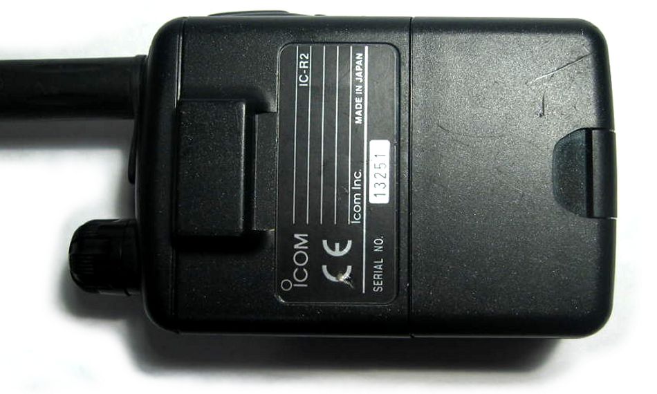
| 08:34, 25 August 2009 | IC-R2 Back1.jpg (file) |  |
71 KB | Tim | Back of the IC-R2 hand held radio scanner. | 1 |
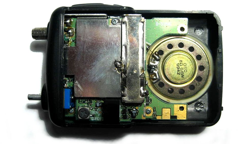
| 08:35, 25 August 2009 | IC-R2 Back2.jpg (file) |  |
88 KB | Tim | Back of the IC-R2 hand held radio scanner with the cover removed. | 1 |
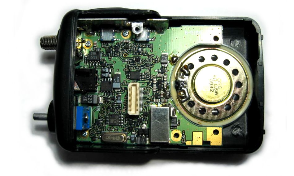
| 08:35, 25 August 2009 | IC-R2 Back3.jpg (file) |  |
86 KB | Tim | Back of the IC-R2 hand held radio scanner with the RF circuit board removed, showing the main circuit board. | 1 |
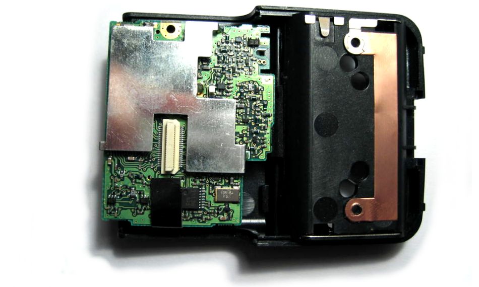
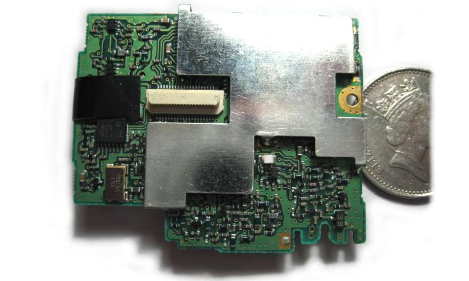
| 08:37, 25 August 2009 | IC-R2 Board1.jpg (file) |  |
78 KB | Tim | Back of the main circuit board in the IC-R2 hand held radio scanner. | 1 |
| 08:38, 25 August 2009 | IC-R2 Board2.jpg (file) |  |
49 KB | Tim | Front of the RF circuit board in the IC-R2 hand held radio scanner. | 1 |
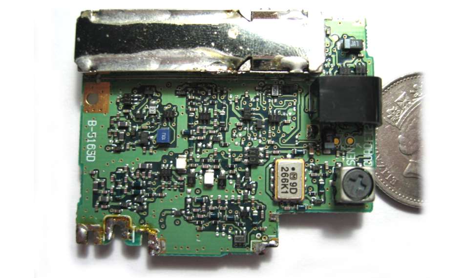
| 08:40, 25 August 2009 | IC-R2 Board3.jpg (file) |  |
57 KB | Tim | Back of the RF circuit board in the IC-R2 hand held radio scanner. | 1 |
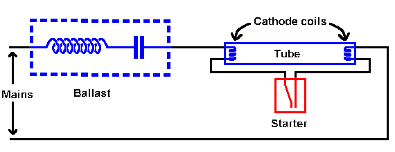
| 23:31, 25 August 2009 | Fluorescent Starter Circuit.png (file) |  |
2 KB | Tim | Circuit diagram showing how a Flourescent Starter connects to a Flourescent tube. | 1 |
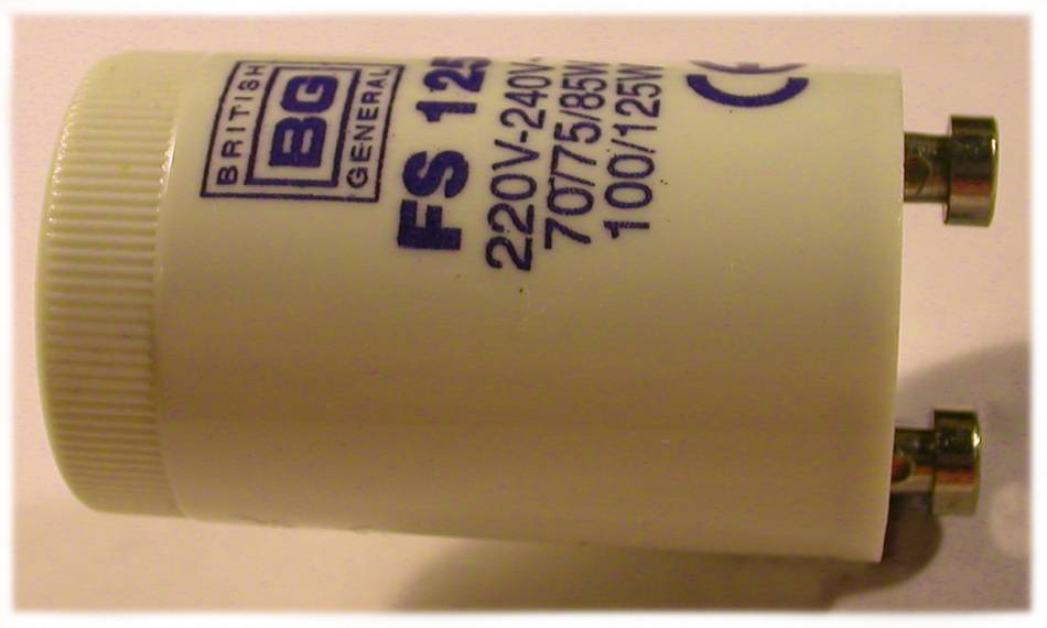
| 23:32, 25 August 2009 | Fluorescent Starter 1.jpg (file) |  |
37 KB | Tim | Flourescent Starter in its case. | 1 |