Neilsen Kellerman Cox Box
The cox box shown here is used by the coxswain of a rowing boat to speak to the crew. The boat is normally fitted with two or three speakers under the seats of the rowers, and the cox is able to speak through these using a headset microphone. In addition, the boat is fitted with a magnetic reed switch under the number 8 rower's seat. This is used to detect how frequently the rowers are taking a stroke.
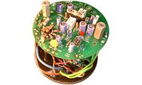
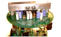
The cox box is shown in the photos below with the case removed. At the top is the front panel - a clear plastic disc with an LCD screen behind it. Two connectors are mounted in this disc for the microphone and boat / charger. The boat / charger connector is an Amphenol Series 44 circular (thanks Malte!), while the microphone connector is a standard BNC socket. A volume control with an 'off' position and a zero/run/hold switch are also mounted in the disc. Below this is a circuit board carrying the digital electronics required to show timing information and stroke rate. The battery pack (6 rechargeable AA cells) are between this and the bottom circuit board, which carries the amplifier and recharging circuitry. The front panel and two circuit boards are spaced with aluminium pillars, and a further pair of pillars hold the heat-sink for the amplifier. This heat-sink is pressed into the bottom of the metal case, and two screws fix the whole assembly to the bottom of this shell. Two Allen screws hold the pillars that separate the front panel and digital circuit board. These must not be removed before the case is opened. (If you've removed these before opening the box then read the text further down).
-
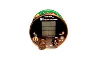 Front of NK Cox box
 -
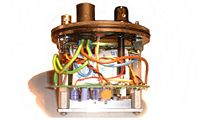 Side of NK Cox box
 -
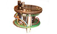 Side of NK Cox box


The photos above show the cox box without the case. The overall layout inside is well thought out, with the bottom amplifier board separated from the more complex digital board, and the heavy batteries sandwiched between these boards in the centre of the case. The amplifier is able to dissipate heat through the heat-sink into the metal case, which is a single shell made waterproof by seals on the bottom screws and a rubber O-ring around the clear plastic front disc. The volume control with on/off switch is mounted in the bottom board, and a rod is used to control this by a knob on the front panel.
-
 NK Cox box Opened up
 -
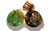
 Amplifier inside NK Cox box
 -
 Heatsink inside NK Cox box


The bottom line of photos show the circuit boards. The components used are beginning to show their age and many, including the LM1896 amplifier chip, are no longer produced. The digital board contains a proprietary micro controller and LCD display, and so in general can only be repaired by Neilsen Kellerman or an associated dealer. From experience, the digital board is generally robust and problems are only encountered when the LCD display is broken. The LM1896 amplifier on the other hand is more prone to failure, with no thermal or short circuit protection (alternative devices were probably more expensive when the cox box was designed). This makes it sensitive to badly wired speakers, so if the amplifier stops working and the batteries appear to be OK, it is likely that this device has died. It is possible to mount a modern amplifier (e.g. TDA2005 or a pair of TDA2003 chips) in its place, which is preferable to replacing the chip with another of the same type. Before you attempt to make the repair yourself, take note of the following text...
OK, if you've got one of these and it needs repairing you've probably already tried to take it apart. If you're like me, you removed everything that you had a tool for and its still as secure as when the cox swings it around by the microphone lead. The mistake (as I found out to my cost) was removing the Allen screws from the front panel. These hold washers in place that separate the front panel from the LCD screen. Once these have been removed, the washers will fall out of place and any further attempt to remove the case will probably crush the screen between the solder side of the digital circuit board and the front panel. If this happens the screen will probably break, leaving you with a glorified coxing amplifier (that rattles). So before you do this it is worth checking out the price of having someone else repair the unit. If they break it they'll take the responsibility and make sure it works at the end of the day. If you've already started to take it apart and got stuck, or you can't get it back together then you could do worse than contact a repair company (e.g. http://www.oarsport.co.uk in the UK).
If you're sure you want to take it apart yourself, see my guide to Taking Apart A Neilsen Kellerman Cox Box.
The circuit on the Amplifier board for the above cox box is shown in the diagram below. The battery is charged via a current limiting resistor, and a diode is used to prevent the battery from illuminating the charging lamp when the charger is disconnected.

The on/off switch integrated into the volume control connects the battery to the amplifier circuit. The digital board is permanently powered, so that the history of ratings is retained when the cox box is turned off, however, the display is only powered when the cox box is turned on. R3 and R4 bias the microphone, with capacitor C3 to prevent feedback. A proportion of the signal (set by the volume control VR2) is then passed into the input of one half of the op-amp bridge. This bridge amplifier is taken from the LM1896 datasheet, and provides a high level of power for the limited single rail supply voltage available. The op-amp connections are given in the LM1986 datasheet below. It is possible to fix a different dual op-amp (or pair of op-amps) to the heat-sink and connect the pins to where the equivalent pins were soldered on the LM1896. Note that the TDA2003 has no equivalent to the bypass pin on the LM1896 and can be ignored. The TDA2005 has a pin labelled SVRR (Supply Voltage Rejection Ratio) that is equivalent to the bypass pin on the LM1896. This connection is used to reduce the power on click. Both the TDA2003 and TDA2005 have output protection and thermal shut down protection, so they should prove more robust than the older LM1896.
If you are only interested in the amplifier part of the cox-box you can either buy a coxing amplifier or build your own. I have put my own design for a Coxing Amplifier in the projects section of my web site.
Links
- My Coxing Amplifier in the projects section of my web site
- Ben Formesyn's Amplifier - Another coxing amplifier design
- http://www.oarsport.co.uk/ - Web site for Oarsport, who sell NK coxboxes and other rowing equipment
- http://www.nkelectronics.com/ - Web site for Nielsen Kellerman, who design and build electronic rowing equipment in the USA
- The Rowing Service - With links related to all aspects of rowing